Permanent System Radar Sites
|
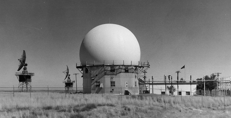
With the outbreak of the Korean War on 25 Jun 1950, a new emphasis on air defense made the Permanent System radar network a high priority and the network rapidly took shape, underwent several expansions, and by the end of 1958 it was essentially complete. The operational areas of the permanent system Aircraft Control & Warning (AC&W) radar sites typically contained a single long-range search radar and two height-finder radars feeding into a standardized operations building. Radarscope operators passed aircraft positions to personnel who plotted the path of aircraft on a plexiglass plotting board with grease pencils. For "unknown" aircraft, weapons controllers could scramble and direct fighter aircraft to identify unknown aircraft and shoot them down if necessary. In October 1949 the Air Force commissioned the Chicago firm of Holabird Root & Burgee to design the entire command & control infrastructure system including the radar sites and command centers. Holabird Root & Burgee designed the Type 2 operations complex to be built at each of the AC&W radar sites. The Type 3 and 4 designs were the Manual Direction Center Operations buildings with the Type 4 being the most common. By August 1951, ADC had emplaced only one AC&W radar squadron with modern, permanent equipment along with the first Type 4 command and control Direction Center at McChord Air Force Base (P-4). At the beginning of 1952, 14 more AC&W squadrons were operational, with the remaining AC&W squadrons and 10 of the 11 command and control Direction Centers nearly complete by the end of 1952. These centers were each assigned to an Air Defense Division. An ADC combat operations center at Ent Air Force Base in Colorado, built in 1954, coordinated the network. Follow-on programs expanded the original 85 site program. It should be noted that some sources refer to the 75 original "P" designated sites and others indicate that there were 85 original "P" designated radar sites. The "P" designation numbers did go to 85 but only 75 of those applied to radar sites, the other 10 were applied to Permanent Radar System Direction Centers. By the end of 1957, just before the SAGE System implementation, there were 182 operational AC&W radar sites with 17 operational manual Direction centers. The breakdown included 17 Direction centers, 75 permanent system sites, 47 gap filler sites, 39 semi-mobile sites, 19 Pinetree Line sites, and one lone Lashup site. Each of the AC&W radar sites was connected to a Manual Direction Center by voice and teletype lines. Each direction center coordinated the activities of a larger geographic area and could manage a battle situation. The direction centers connected to one of three (East, Central, West) command centers, and the three command centers were connected to the Headquarters command center in Colorado Springs, Colorado. This system was a manual system dependent on human interactions at every level from detection to intercept.
SAGE System and the Permanent Radar SystemAs the Permanent System came to maturity between 1958 and 1960, it was converted to the SAGE System site by site. This was done by adding a large SAGE Annex to the existing operations buildings and as a follow-on, converting one of the existing radio buildings (usually the transmitter building) into a new Ground-Air Transmit-Receive (GATR) radio building. Within the SAGE Annex, an FST-2 was installed to process and send radar data to the FSQ-7 direction center computer over communication circuits. Most permanent System radar sites converted to SAGE operation were designated with a "Z" number like Z-100 for the prime site and Z-100A for an associated gap-filler. The expectation in 1960 was that there would be 194 prime radar sites, 207 gap-filler sites and that 99 of the prime sites would have Frequency Diversity (FD) radar sets. Both the gap-filler program and the FD radar programs were problematic. Virtually all of the gap-fillers were closed by the mid-1960s and the very expensive FD radars hung on until the antenna problems became so costly that they were shut down and replaced with smaller sets or the sites were simply closed. One example of the FD radar troubles was the Mount Hebo Air Force Station FPS-24 that had to be replaced with a smaller FPS-27. Sources:
|


